
|
|
||||
|
|
|
||||

|
|
||||
Sound Card EEG (ScEEG) Technology
This web site is focused on sound card EEG hardware and software experimentation to create a Brain-to-Computer Interface (BCI). Several types of EEG units have been built to date, a dual channel AM unit, a dual channel FM unit, A four channel AM unit, and a four channel multiplexed unit. The FM unit uses approximately 4.5 kHz of audio spectrum per channel while the AM unit uses approximately 2 kHz of spectrum (with some guard band allocation) per channel.
The first attempt in building a prototype sound card EEG unit was begun in July 2005 . The first unit consisted of a two channel AM modulated version with a built-in power supply. It is compatible with 12-volt power cubes. There were several breadboards built before the final two boards (input amplifier and modulator) versions were completed. The AM version was successful in achieving approximately 65 dB of dynamic range performance. An existing oscilloscope software application was modified to accept the modulated signal from the prototype.
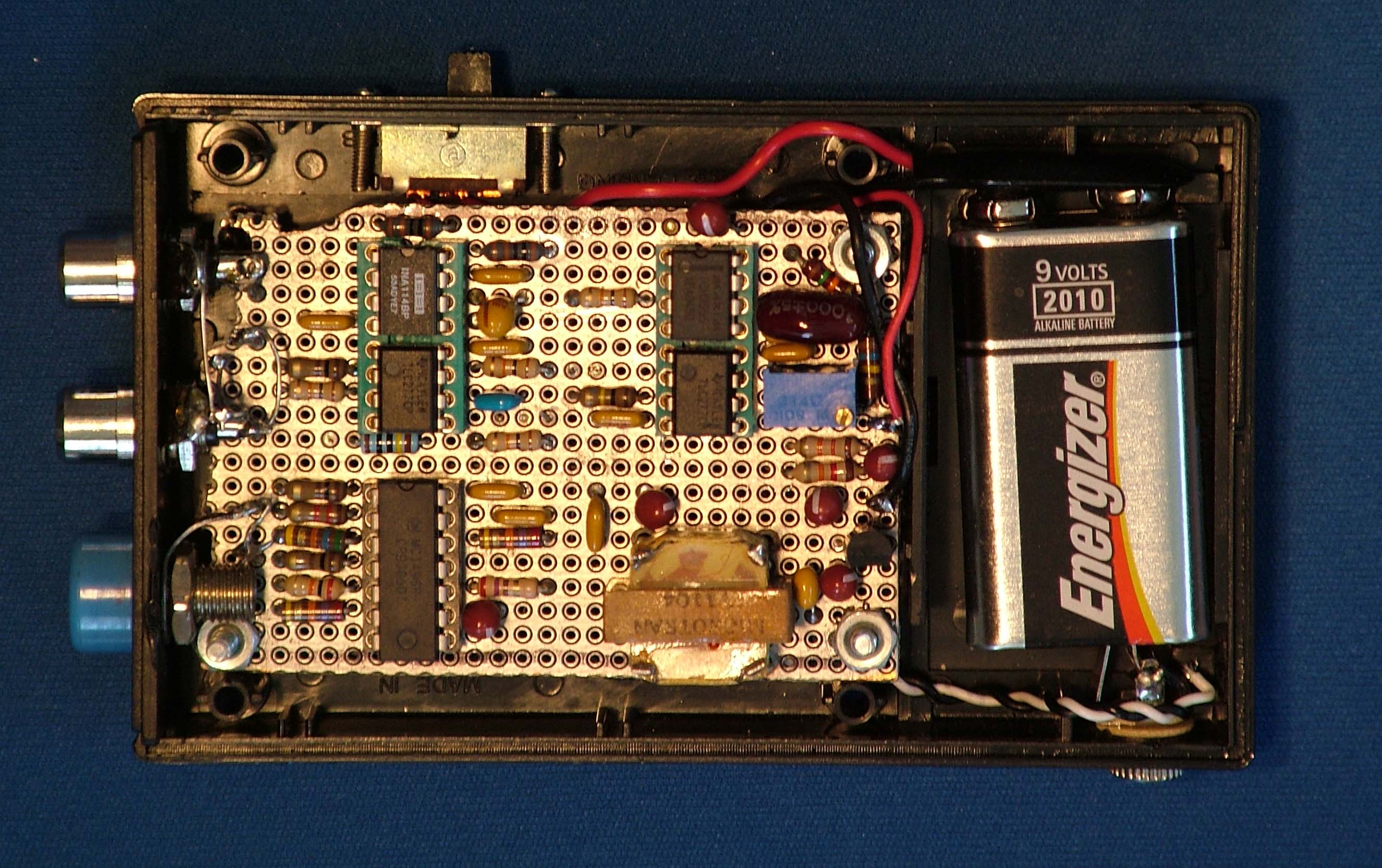
The second prototype was a single channel AM unit that reduced the modulation circuitry and the size of the unit was reduced to 2" by 4". The unit also included onboard regulators and was operated from a 9-volt battery. The unit design also switched from an analog local oscillator (LO) to a digital version (square wave oscillator). This reduced both the size and power consumption of the unit.
The third breadboard and then prototyped was a dual channel FM unit and due to reduced circuitry of implementing the FM modulation was built into the 2" by 4" enclosure with a 9-volt battery included. The total current drain is approximately 6.5 ma. The unit uses two CMOS digital local oscillators. The dual channel AM and FM units now achieve about 80 dB of dynamic range performance. Current drain is less than 6 ma at 9 volts DC.
A new software application (EEGProbe) was developed specifically for EEG display and instrumentation. The software is able to receive data from both AM and FM units. The software incorporates individual channel gain and offset controls with a real time strip chart and vertical FFT displays. A built in variable bandwidth filter can be adjusted by moving cursor lines about the spectrum displays. A second software package, Neuroprobe, provides biofeedback in the form of MIDI or Wave sounds along with the spectrum and waterfall displays. A third application, Keyboard2, is used with the eye cursor output screen of the BioShpere program. The second application, NeuroProbe has a graphical user interface similar to BrainBay. A 1.2 GHz Pentium computer is recommended for running the software applications. The main application screens are shown below:
|
|
|
|||||||||
|
|
|
|
|||||||||
A description of the theory of operation of the AM and FM modulation schemes and the prototype development (with pictures of the units) can be downloaded from EEG Probe Project (a 2.5 meg PowerPoint presentation, it takes a while to download). The schematic of the Dual Channel AM prototype unit, revision 6 has been completed. The Dual Channel FM unit schematic, revision 5, has been completed. The latest software for the prototypes can be downloaded from EEG Probe Install , NeuroProbe Install, and Keyboard Install. The software files will be self-extracting Zip files. After the install files have been extracted from the Zip file to the directory of your choice, run the Setup.exe programs to install the applications. The prototypes to date are simply handcrafted units. If there is enough interest in the sound card concept, printed circuit boards can be built and made available. The designs are simple enough that through-hole technology could be use for kit building.
The latest version of software for the sound card EEG units, NeuroProbe, has been completed and is being tested. It supports both multiplexed (up to 8 channels) and non-multiplexed (up to 4 channels) designs. The input bandpass filtering is programmable and therefore supports all versions of the sound card units. The software incorporates all of the neuro-feedback applications developed in the BioShpere program but has a graphical user interface to configure the program operation. The program capabilities include sending and receiving EEG data via the Internet using TCP/IP, UDP/IP protocols, and an interface to the NeuroServer.
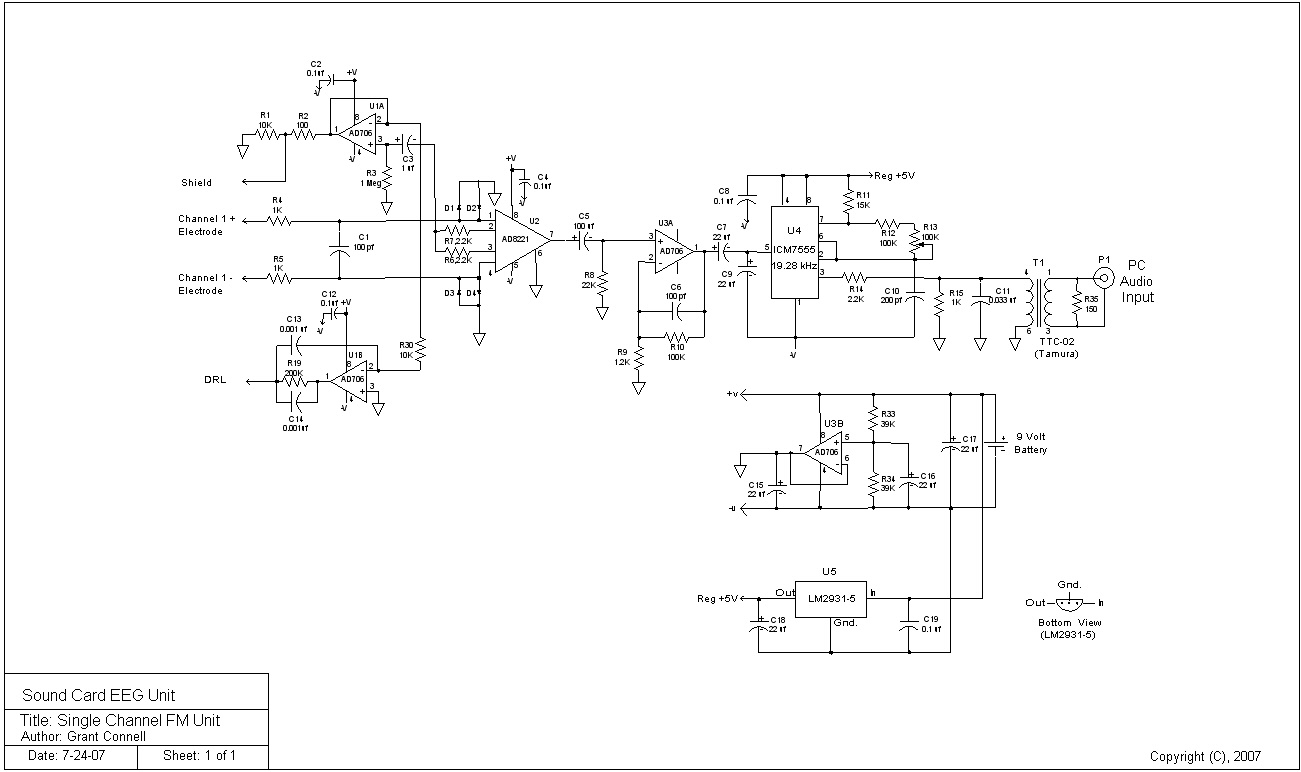
Single Channel FM Unit
There are many applications for EEG units that do not require multiple channels. A low power, good performance EEG unit can be built using the FM technique:
1. 1 EEG signal channel
2. Sample rate = 256 Hz
3. Current drain is approximately 4.5 ma. from a 9 volt battery (70-80 hours of
battery life)
4. Dynamic range is greater than 72 dB (0.25 uv-pp to 1.25 mv-pp)
5. Unit size is 2-1/2inches by 4 inches
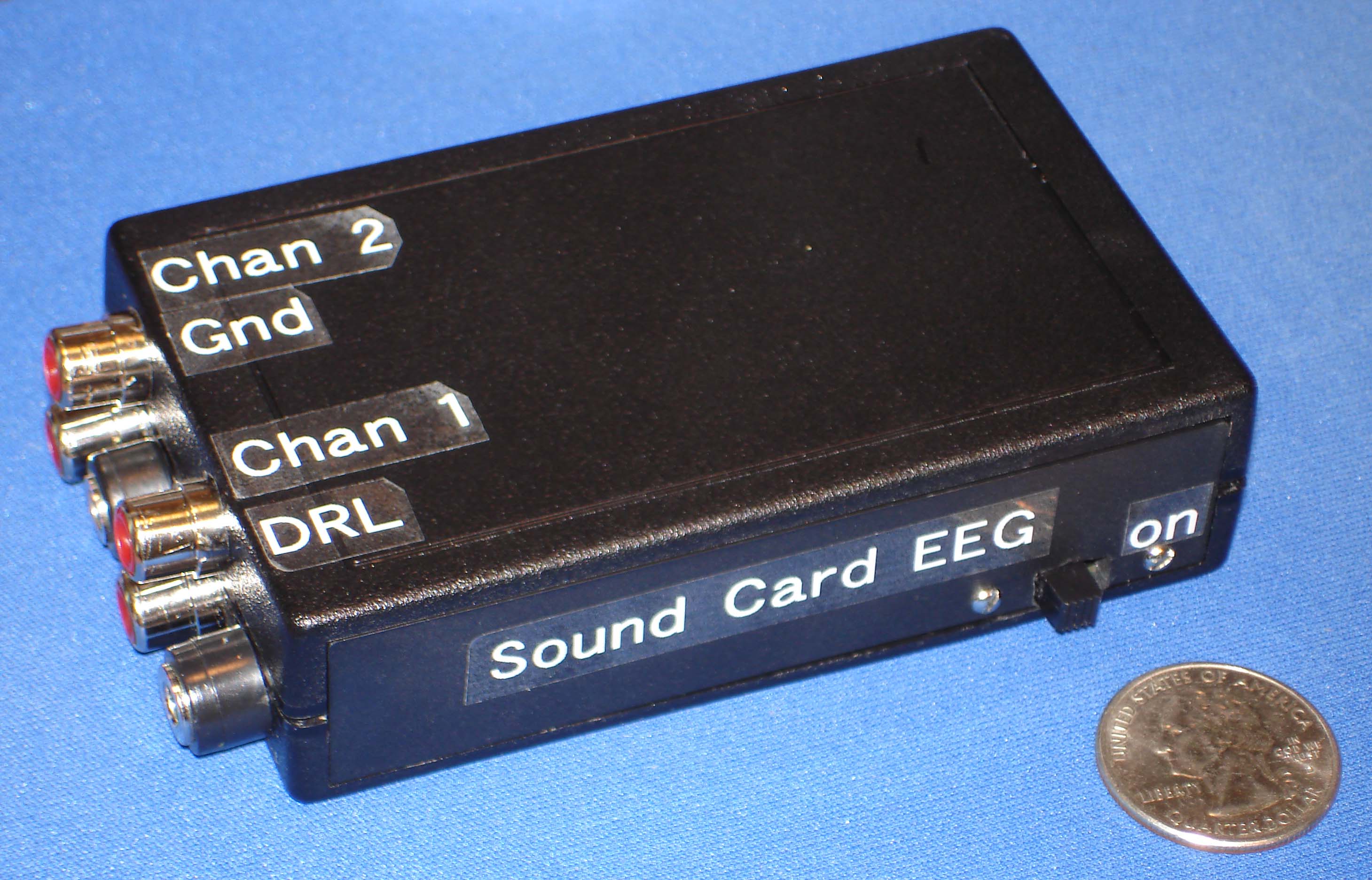
6. Interface to the electrodes are two RCA phono jacks plus DRL plug
7. Microphone (mono) input to the PC
8. Schematic for the unit,
Single Channel FM Unit.
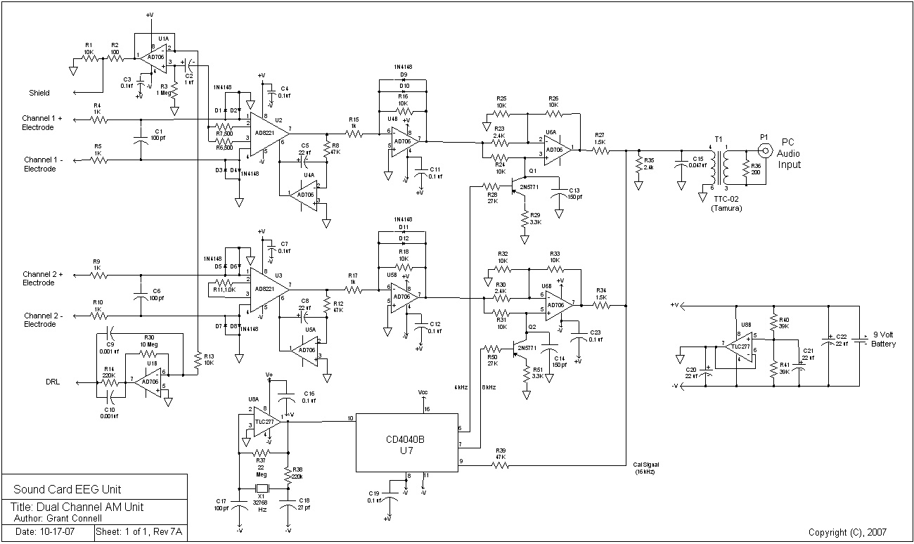
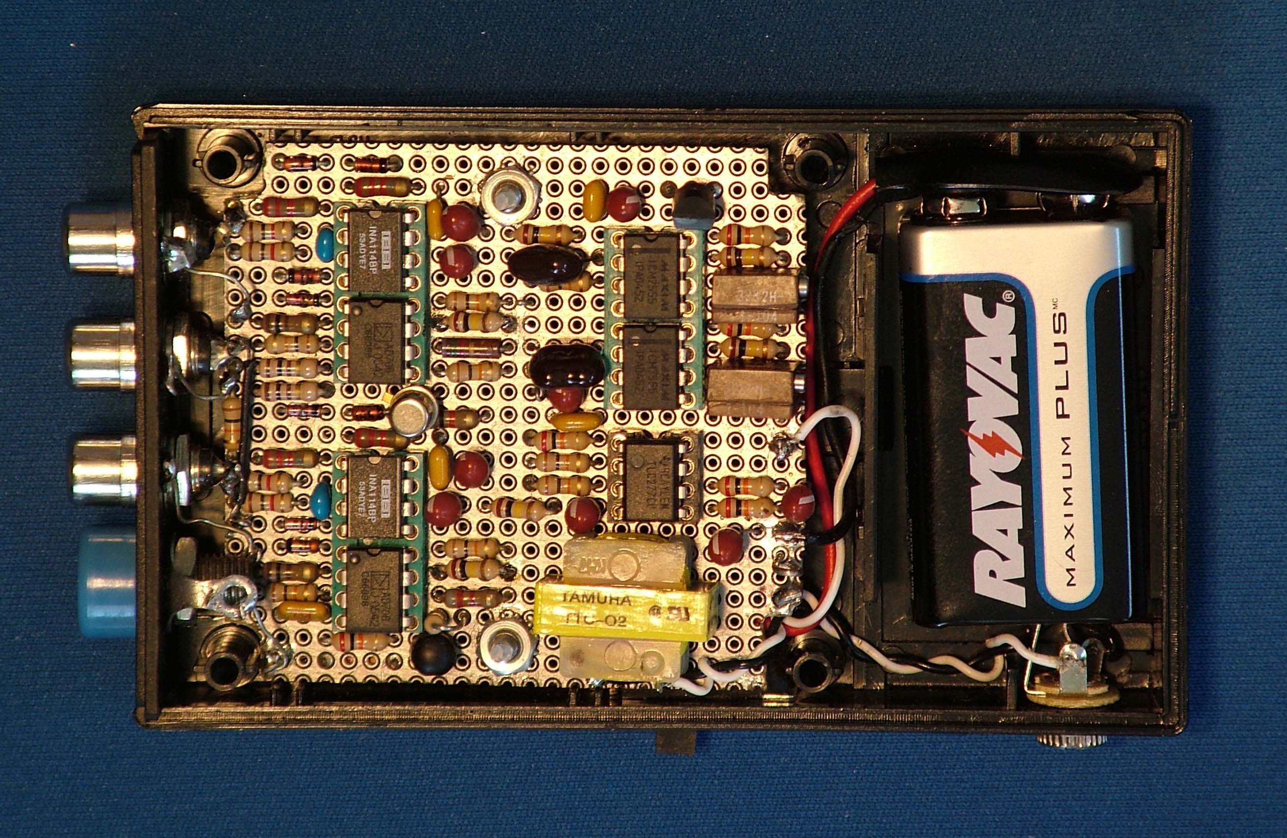
Two Channel AM Unit
1. 2 EEG signal channels
2. Sample rate = 256 Hz to 4096 Hz (software selectable)
3. Current drain is approximately 6.5 ma. from a 9 volt battery (40-50 hours of
battery life)
4. Dynamic range is greater than 90 dB (0.10 uv-pp to 1.25 mv-pp)
5. Unit size is 2-1/2inches by 4 inches
6. Interface to the electrodes are four RCA phono jacks plus DRL plug
7. Microphone (mono) input to the PC
8. Schematic for the unit,
Dual Channel AM Unit
9. Bill of Materials for the unit, BOM
, Revision 2
Marco Vettorello has prototyped a dual channel AM design (Rev 7) with a
schematic and layout in Eagle CAD. He has graciously provided the design for
this web site. Marco's two channel AM design;
Eagle Design Package.
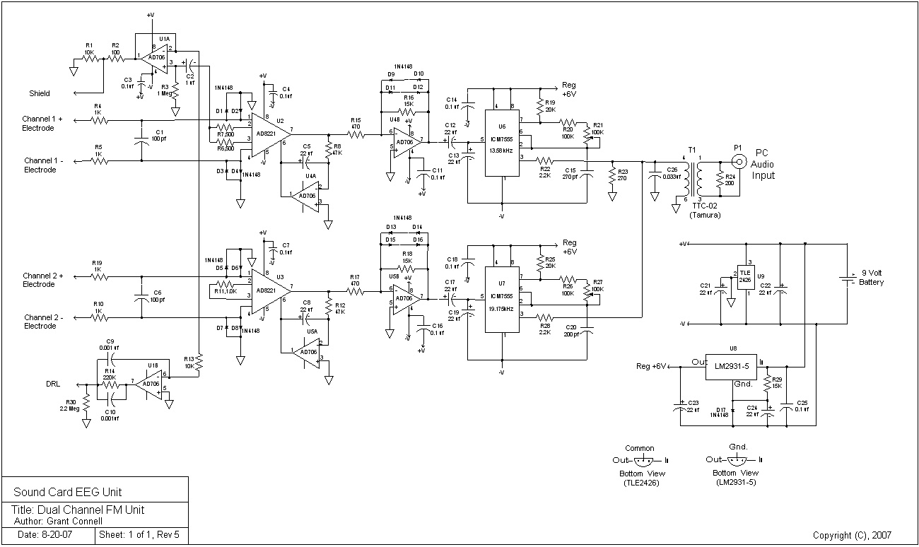
Two Channel FM Unit
1. 2 EEG signal channels
2. Sample rate = 256 Hz
3. Current drain is approximately 6.0 ma. from a 9 volt battery (40-50 hours of
battery life)
4. Dynamic range is greater than 80 dB (0.25 uv-pp to 1.25 mv-pp)
5. Unit size is 2-1/2inches by 4 inches
6. Interface to the electrodes are four RCA phono jacks plus DRL plug
7. Microphone (mono) input to the PC
8. Schematic for the unit,
Dual Channel FM Unit
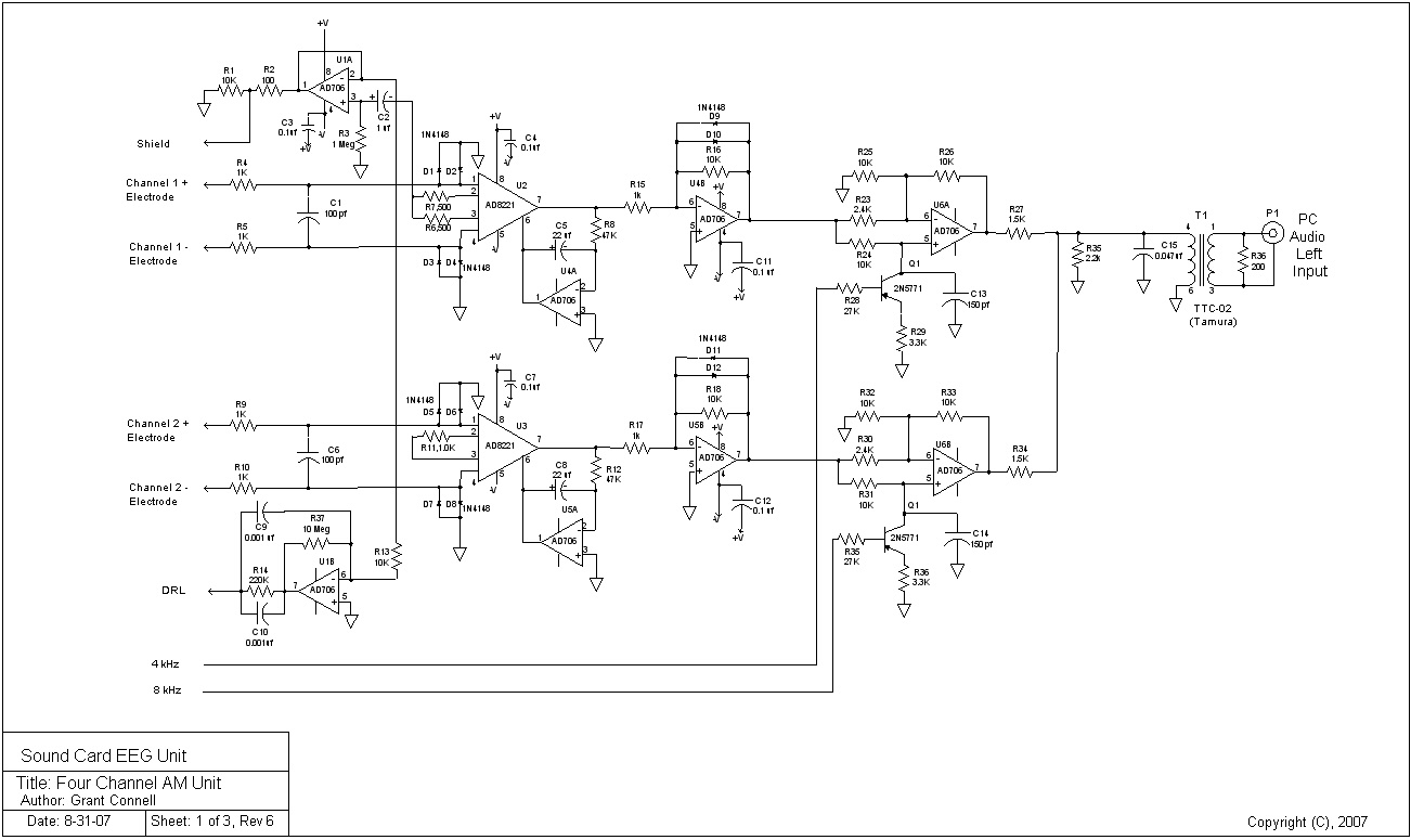
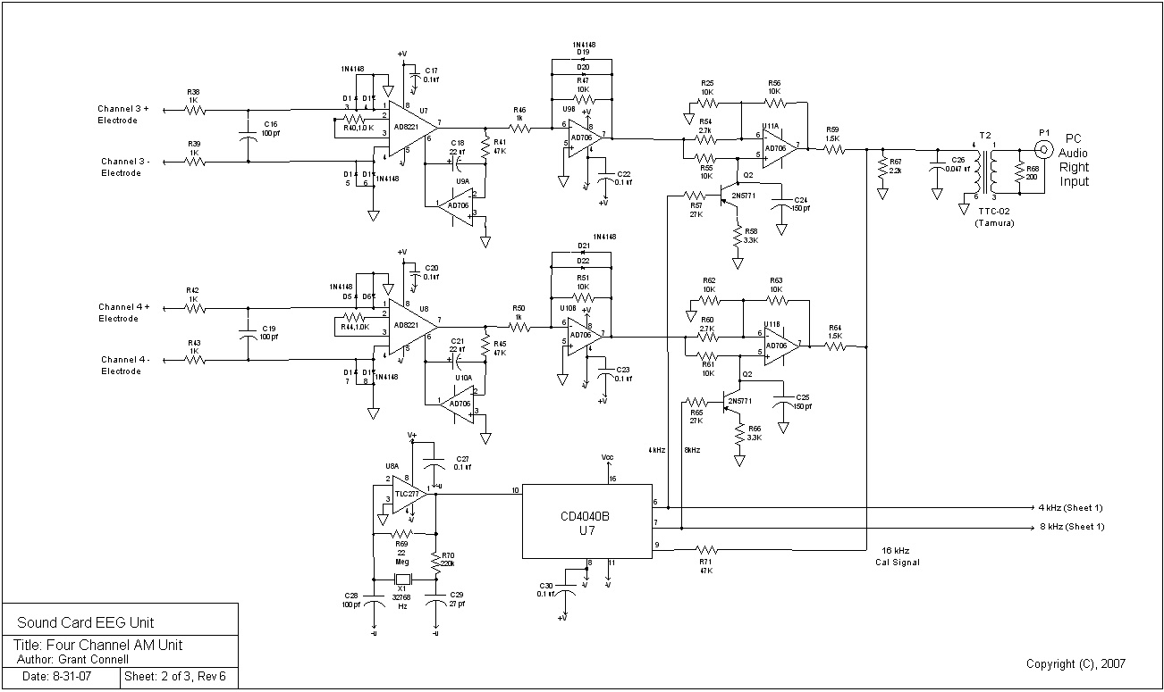
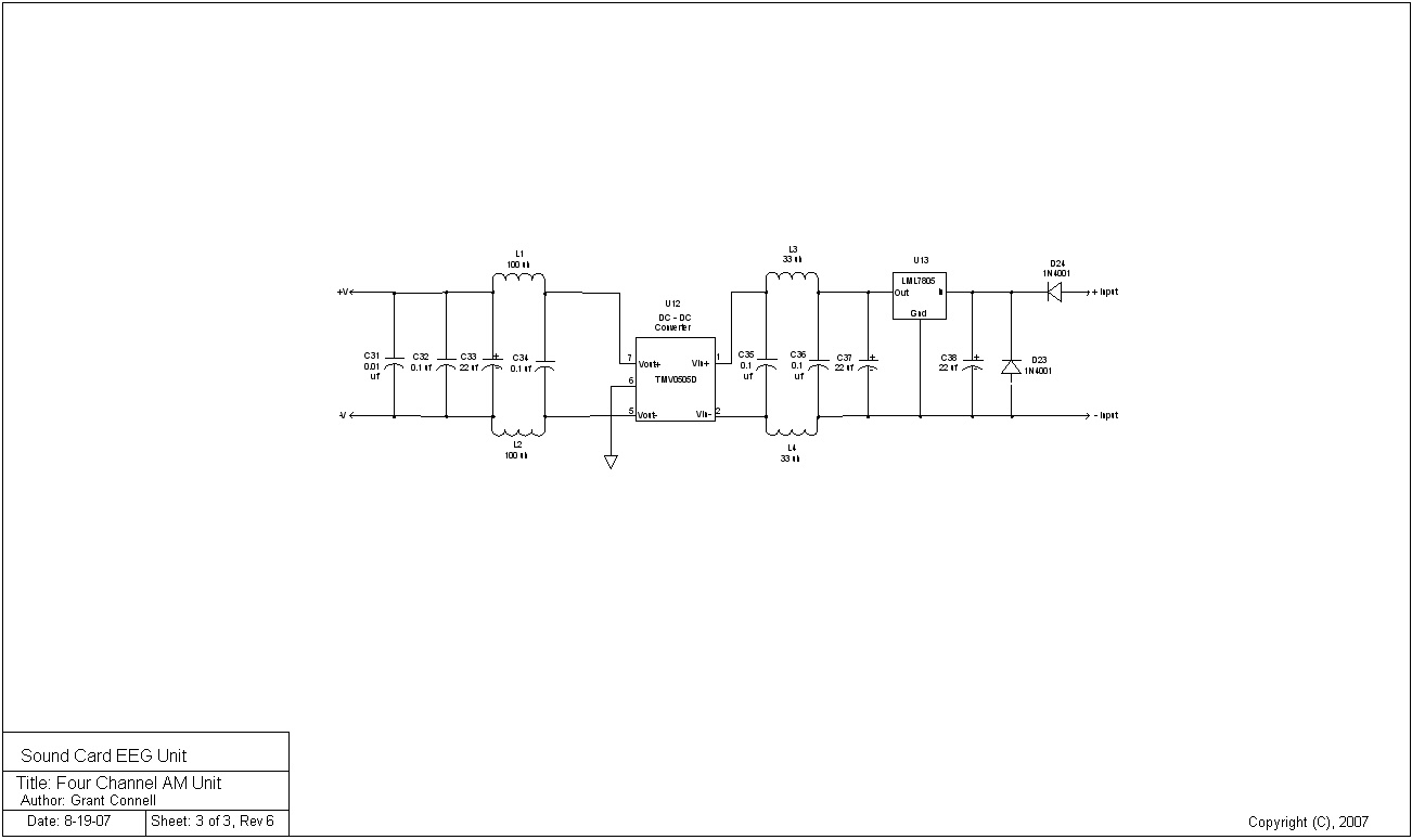
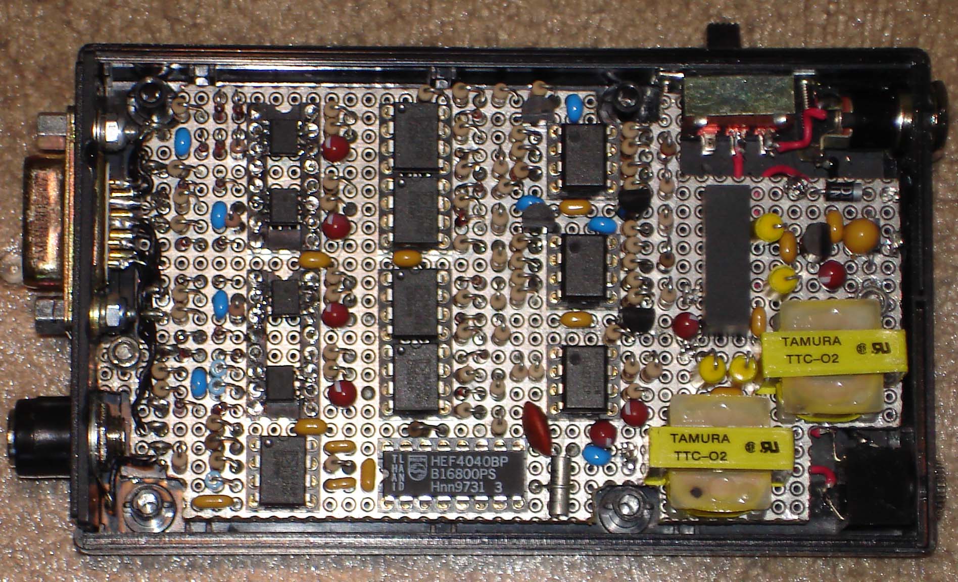
Four Channel AM Unit (advanced design)
1. 4 EEG signal channels
2. Sample rate = 256 Hz to 4096 Hz (software selectable)
3. Current drain is less than 45 ma. from a 9 volt DC power cube
4. Dynamic range is greater than 90 dB (0.10 uv-pp to 3.5 mv-pp)
5. Channel cross-talk isolation is greater than 55 dB
6. Unit size is 2-1/2 inches by 4 inches (prototyped), see pictures
7. Interface to the electrodes is a 9-pin D connector
8. Microphone (stereo) input to the PC
9. Schematic for the unit,
Sheet1,
Sheet2,
Sheet3
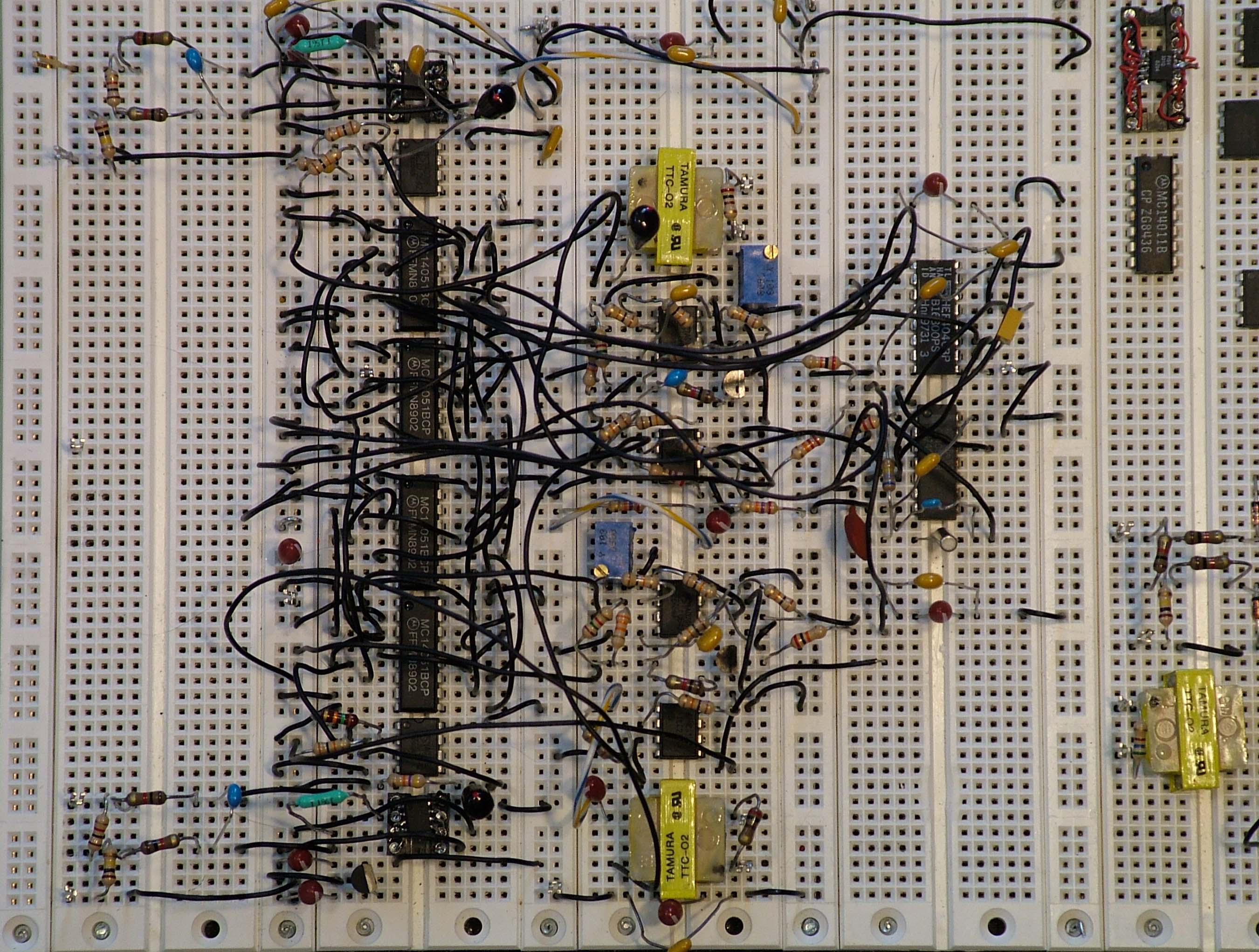
The main advantage of this unit is the higher sample rates while the disadvantage is the requirement of a stereo input to the PC along with two isolation transformers (see the picture of the breadboard unit).
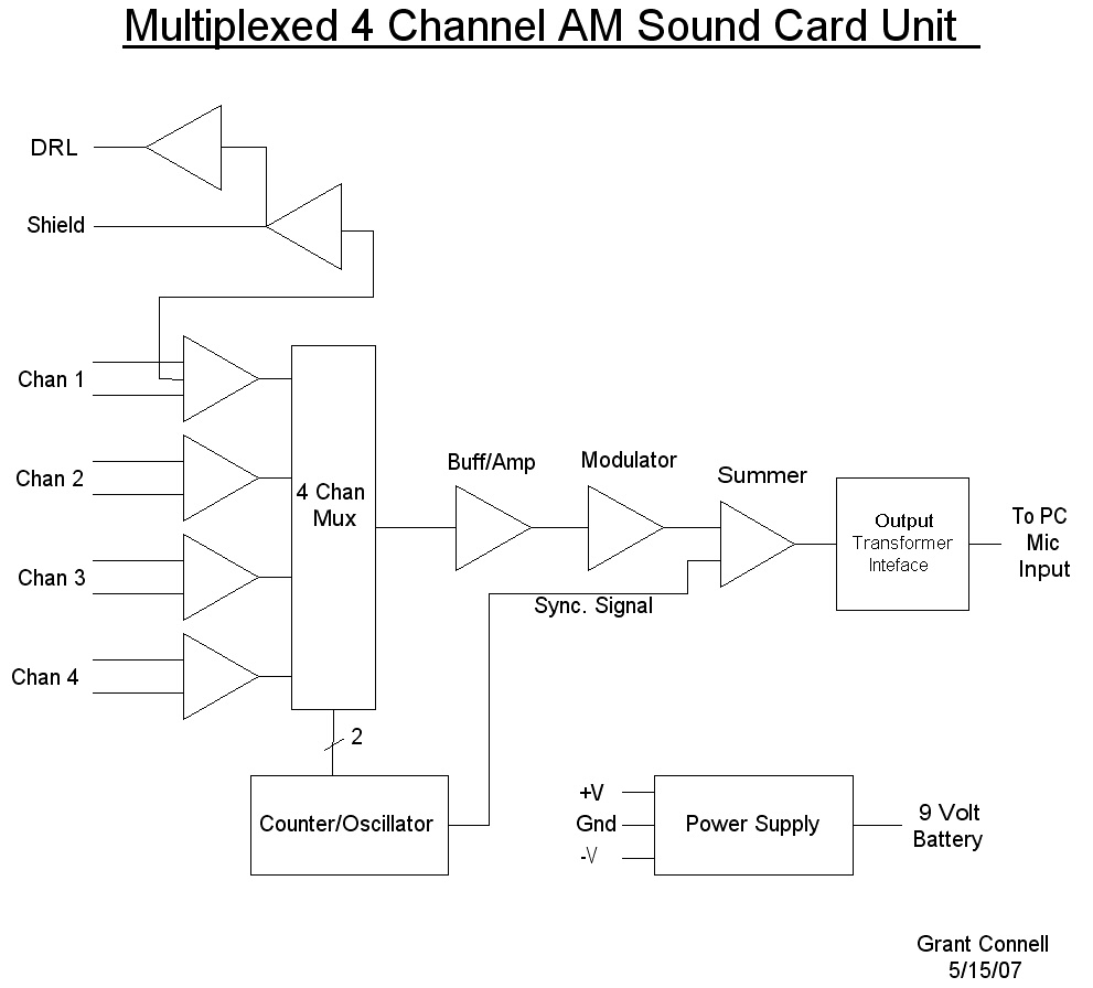
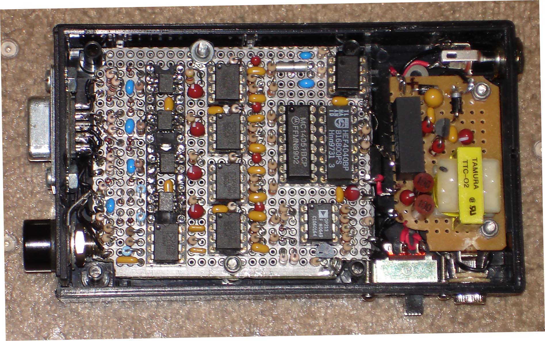
Multiplexed Designs:
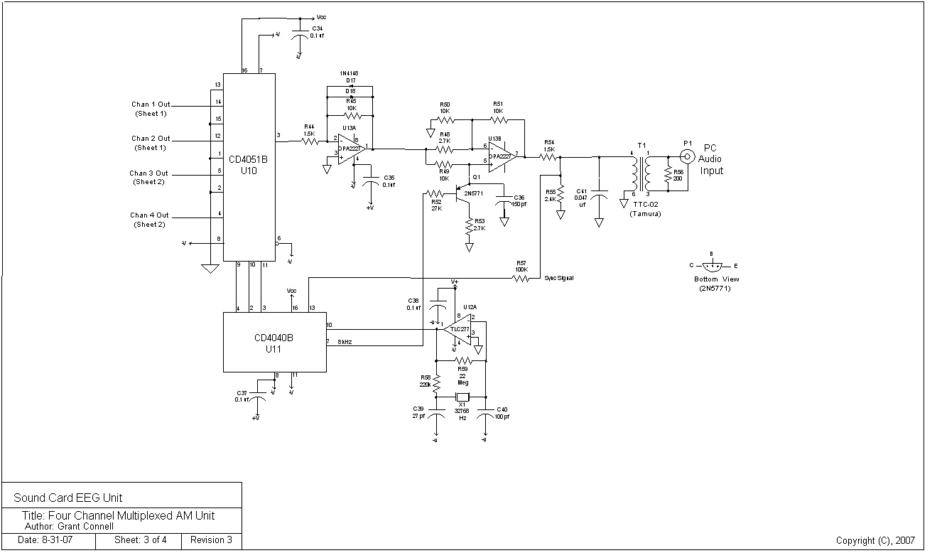
The current versions of the sound card EEG units combine input multiplexing with AM modulation techniques. CMOS multiplexers and logic keep the power consumption to minimum levels. A 16 channel version has been bread-boarded and a 4 channel version prototype has been built (see EEG unit pictures). A block diagram of the 4 channel design shows its simplicity. The specifications for the 4 channel EEG multiplexed AM design is listed as follows:
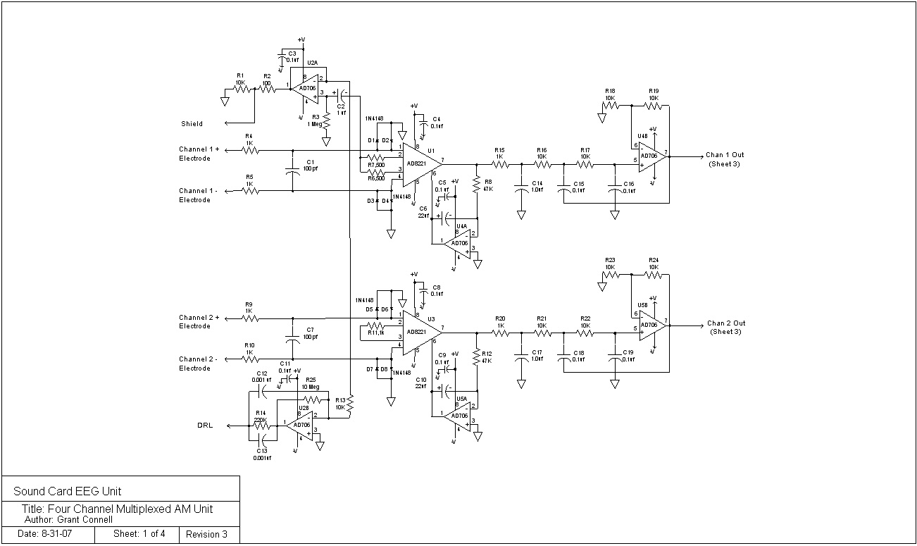
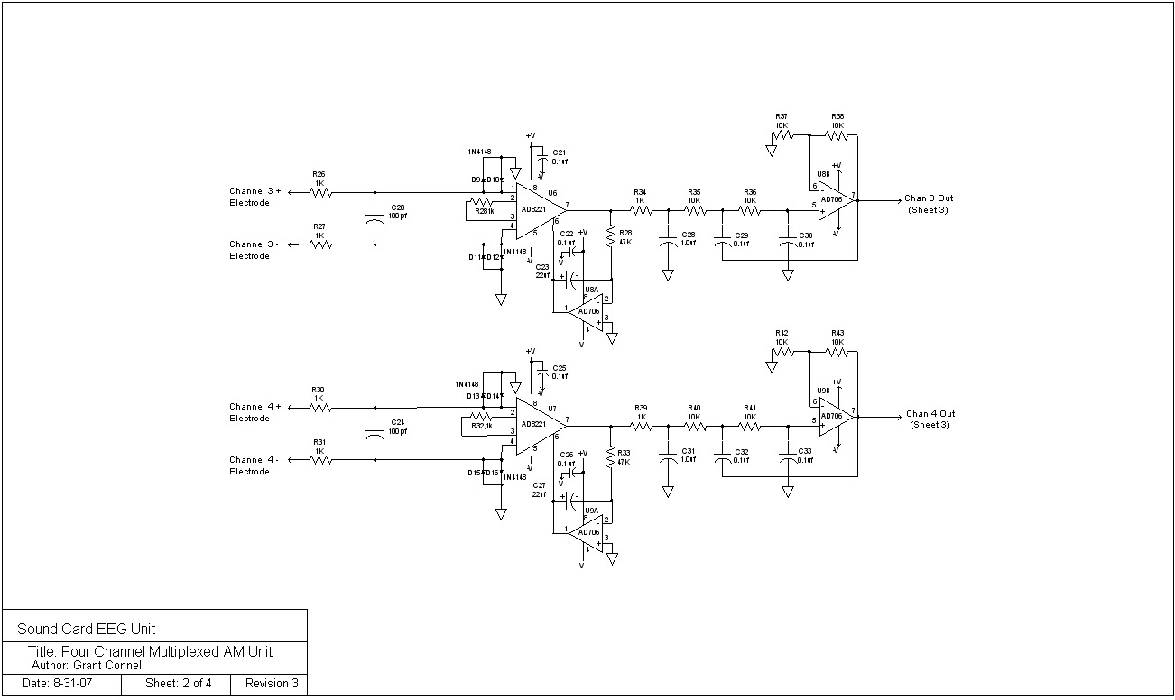
Four Channel Multiplexed AM EEG Unit
1. 4 EEG signal channels
2. Sample rate = 256 Hz
3. Current drain is less than 45 ma. from a 9 volt DC power cube
4. Dynamic range is greater than 90 dB (0.10 uv-pp to 3.5 mv-pp)
5. Channel cross-talk isolation is greater than 55 dB
6. Unit size is 2-1/2 inches by 4 inches (prototyped), see pictures
7. Interface to the electrodes is a 9-pin D connector
8. Microphone (mono) input to the PC
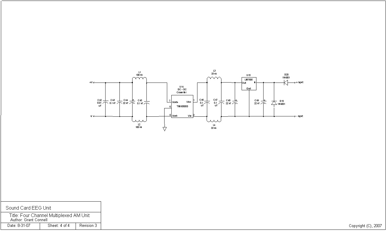
9. Schematic for the unit,
Sheet1,
Sheet2,
Sheet3,
Sheet4
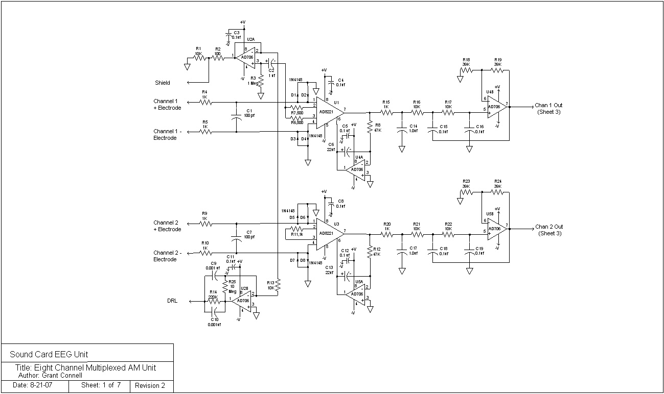
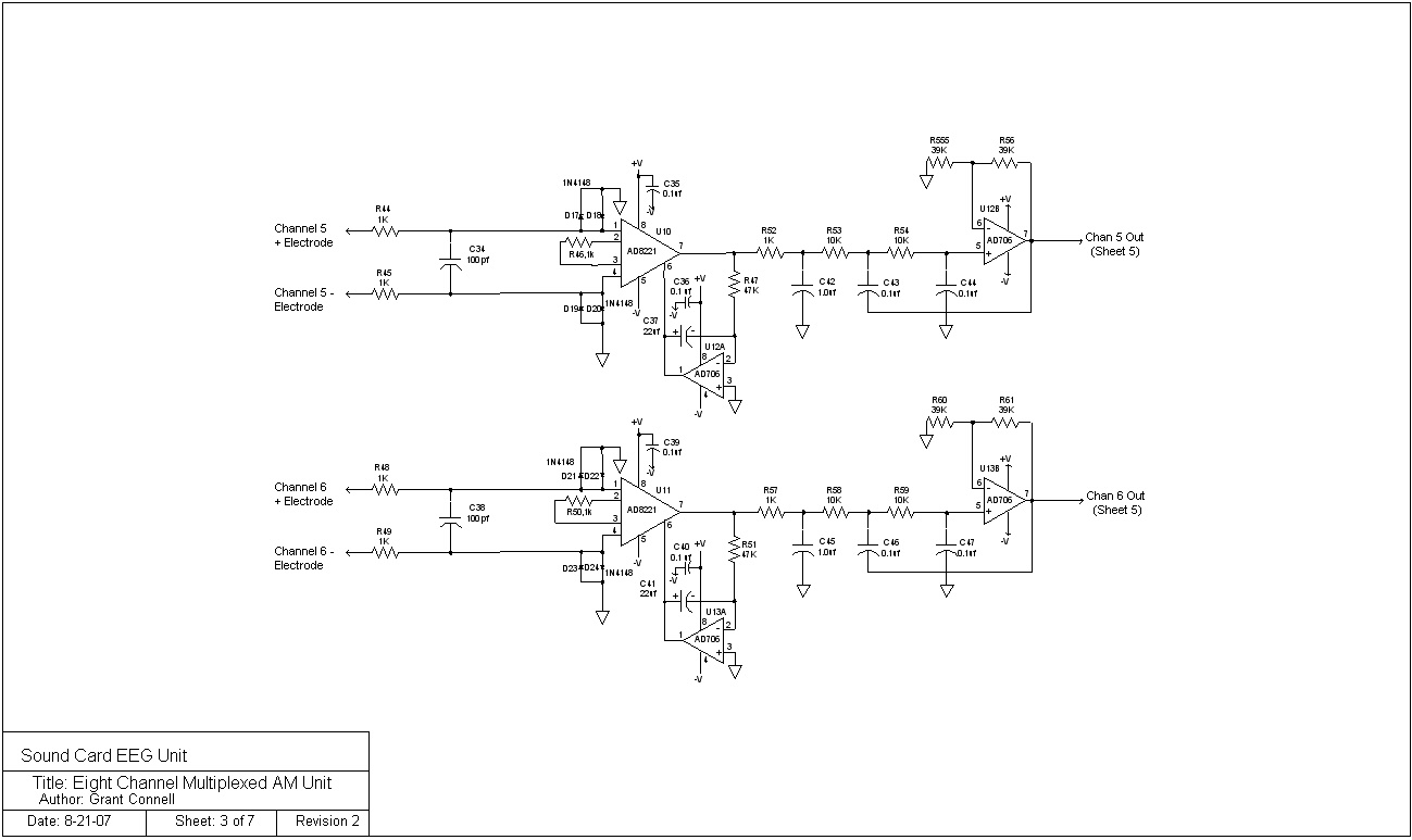
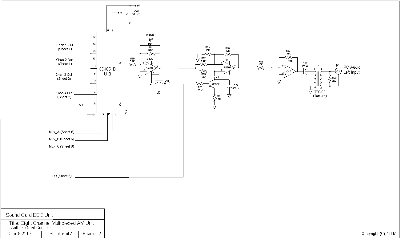
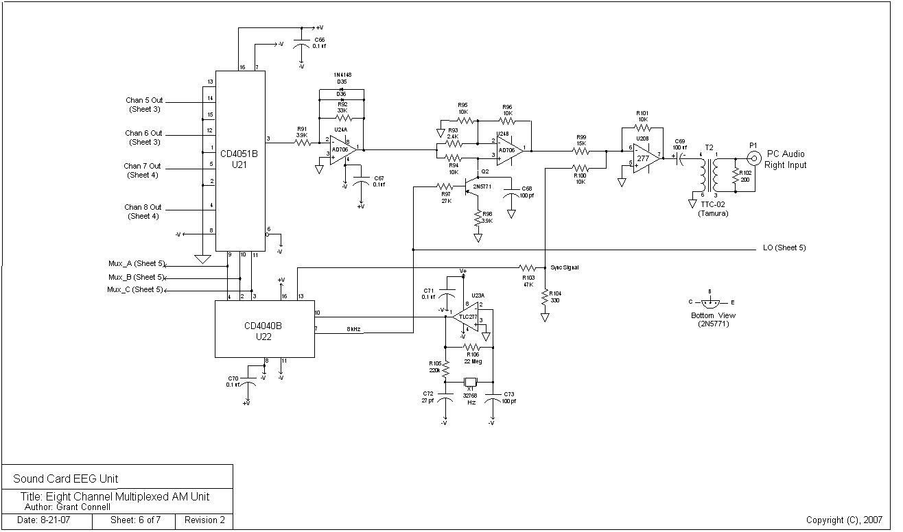
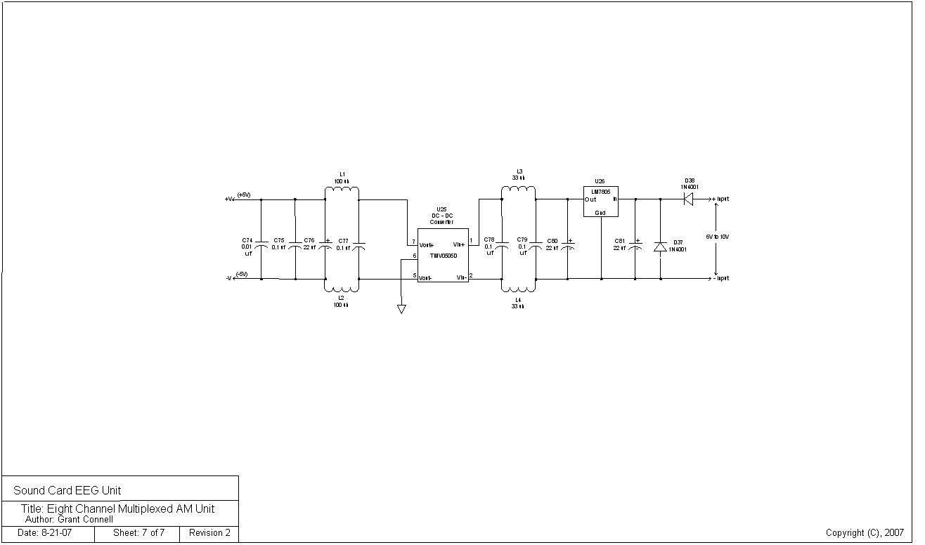
Eight Channel EEG Unit
The eight channel unit expands the multiplexer to handle 8 channels with channel 1 still being the reference for the shield and the DRL signal. The unit outputs a stereo signal to the PC. The unit works a two 4 channel multiplexers in operating in parallel. For laptop computers a sound card with a line input can be purchased for about $70 US dollars. The advantages of the design is that the sample rate is still high (256 Hz). An isolated power supply (6-12 volt DC) is recommended. The disadvantage is that there is now a stereo input to the PC. The specifications for the 8 channel EEG multiplxed AM design is as follows:
1. 8 EEG signal channels
2. Sample rate = 256 Hz
3. Current drain is less than 60 ma. from a 9 volt DC power cube
4. Dynamic range is greater than 90 dB (0.10 uv-pp to 3.5 mv-pp)
5. Channel cross-talk isolation is greater than 55 dB
6. Unit size is 4 inches by 6 inches
7. Interface to the electrodes is a 15-pin D connector
8. Line (stereo) input to the PC
9. Schematic for the unit,
Sheet1,
Sheet2,
Sheet3,
Sheet4,
Sheet5,
Sheet6,
Sheet7
The schematic for the 4 channel multiplexed AM unit (revision 3) has been completed. The design is similar in performance to the two channel units with the sensitivity and dynamic range being slightly better than the two channel AM unit. Although the input amplifiers are the AD8221 versions, the INA114 may be substituted with about 4 ma. more current drain. This would allow for a completely through-hole design. The schematic for the 8 channel stereo unit (revision 2) has also been completed.
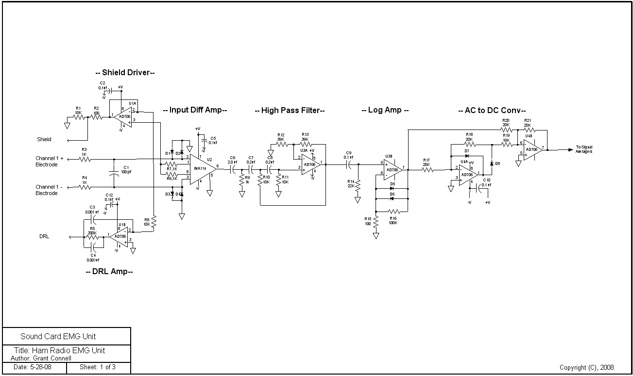
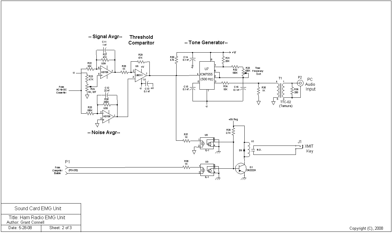
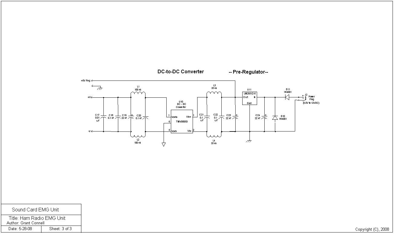
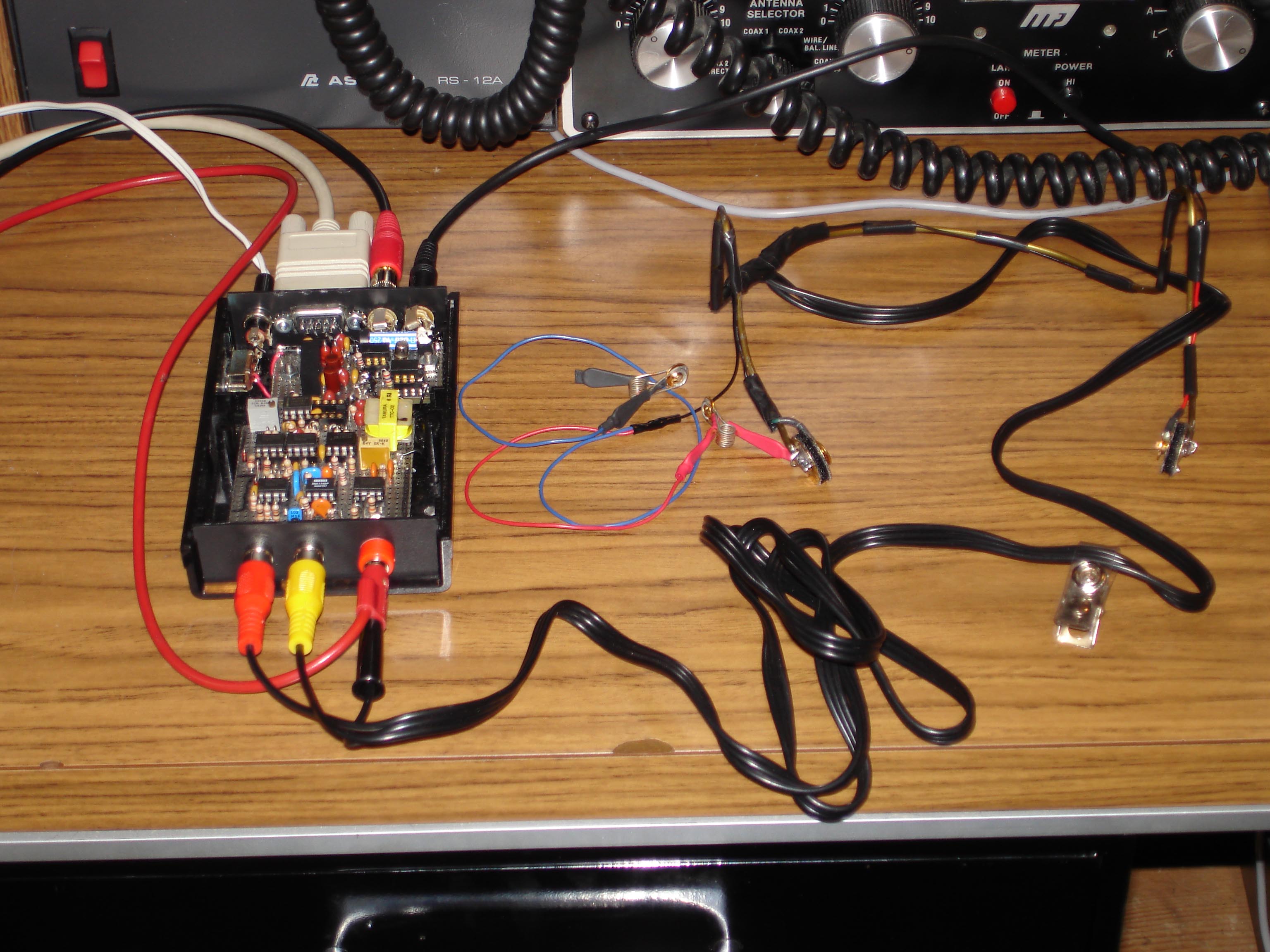
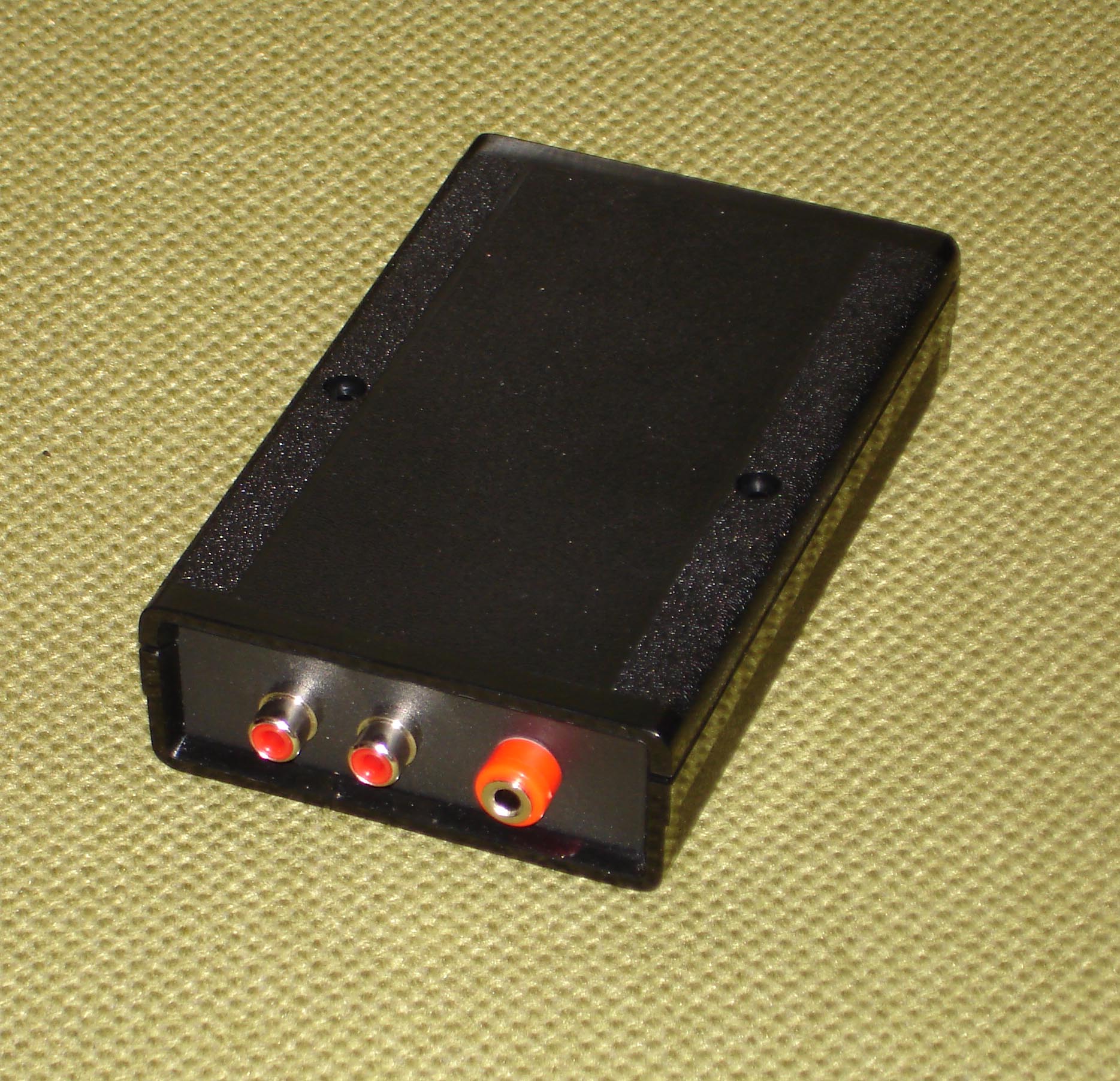
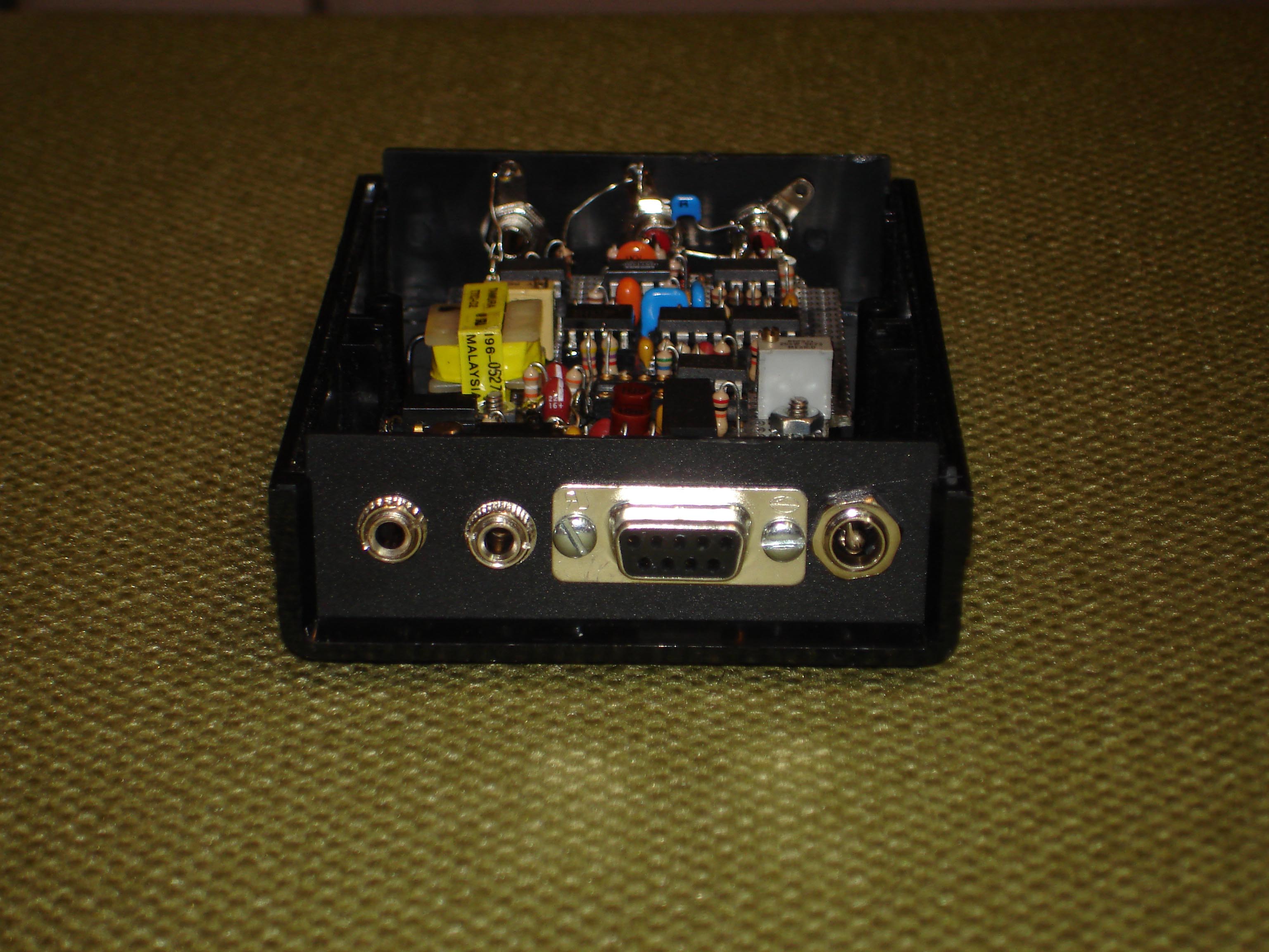
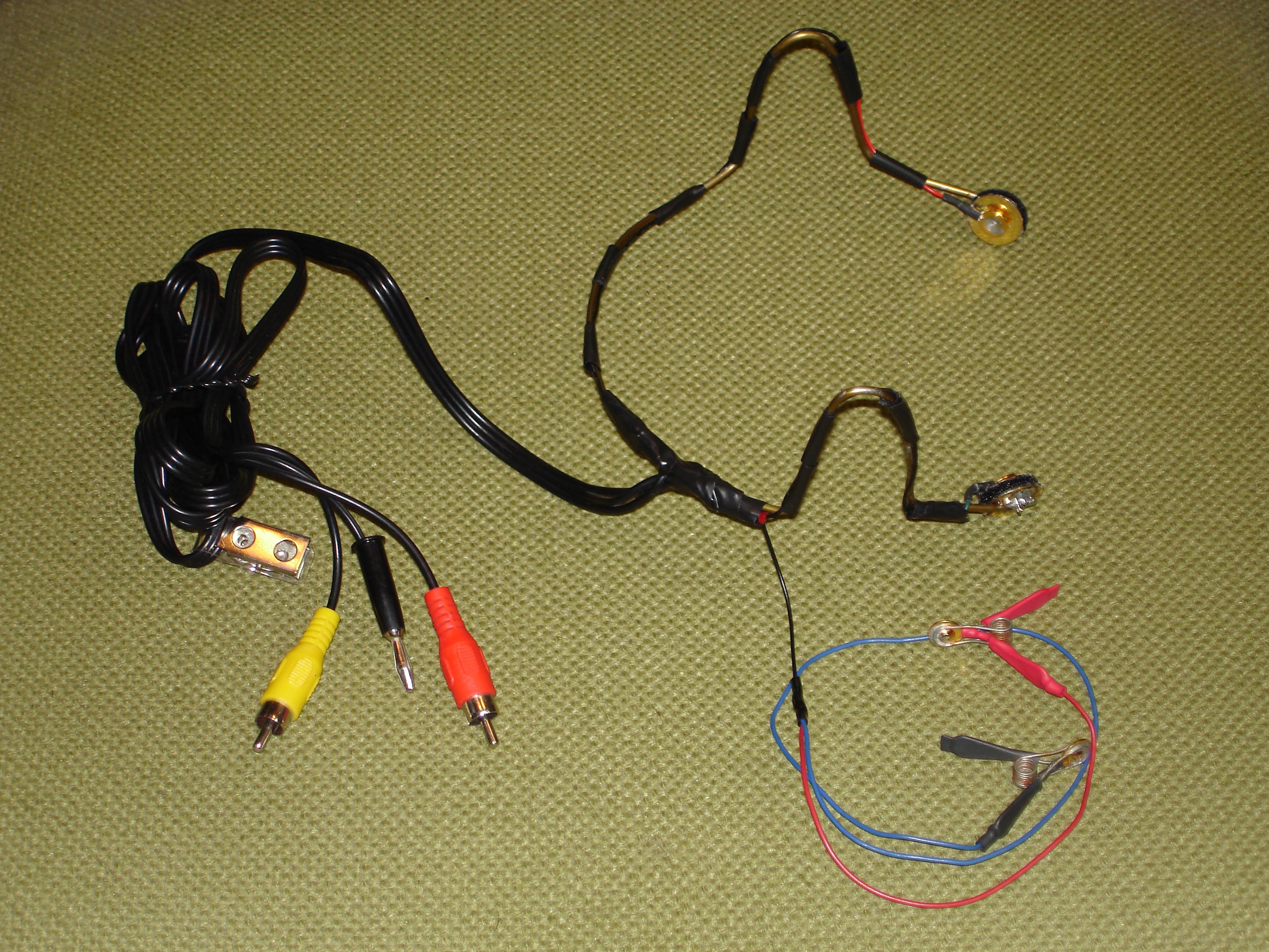
Single Channel EMG Unit, Ham Radio Version
The single channel EMG unit uses a low noise input amplifier and a high gain stage to drive a 440 Hz oscillator to detect EMG muscle signals from the jaw. The circuits also drive a relay to key a radio amateur transmitter. The NeuroProbe software has been modified to accept the tone oscillator and provide Morse encoding for cursor control and text input. A future article will describe the complete circuit configuration between the EMG unit, the computer, and the radio transceiver.
1. 1 EMG signal channel
2. Sample rate = 1024 Hz
3. Current drain is less than 60 ma from 7 volt power cube
4. Interface to the electrodes are two RCA phono jacks plus DRL plug
5. Microphone (mono) input to the PC
6. Block diagram of the hardware,
Diagram
6. Schematic for the unit,
Sheet1,
Sheet2,
Sheet3
7. Bill of Materials for the unit,
BOM_EMG
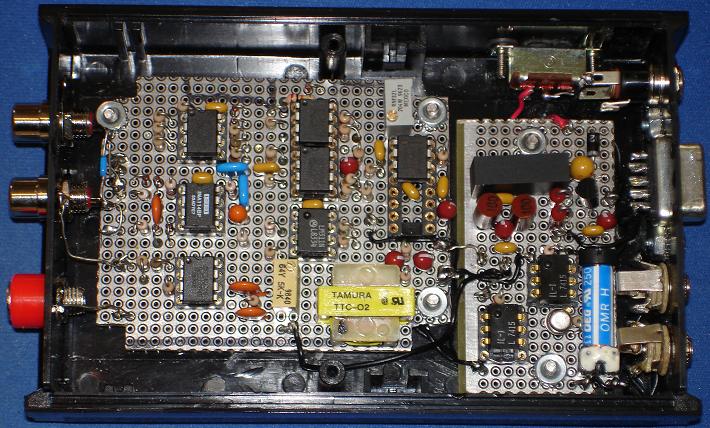
8. Picture of EMG Unit,
EMG Picture1,
EMG Picture2, EMG
Picture3, EMG
Picture4,
EMG
Electrode Configuration
EEG Unit Pictures (all types)
Single
Channel AM Unit (first design, obsolete)
Dual Channel
AM Unit (Rev 4)
Four Channel
AM Unit (Rev 6)
Four Channel Multiplexed AM Unit
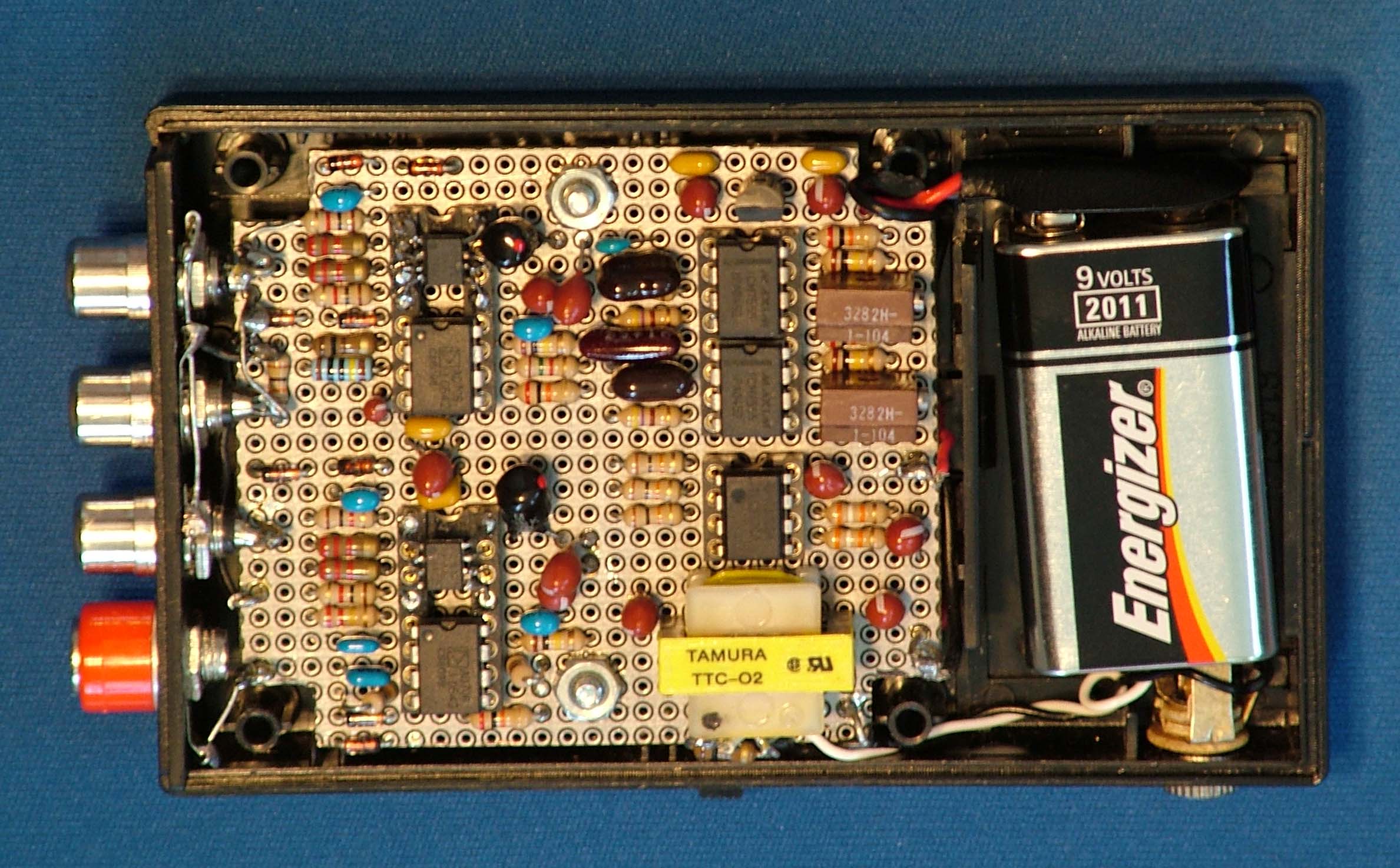
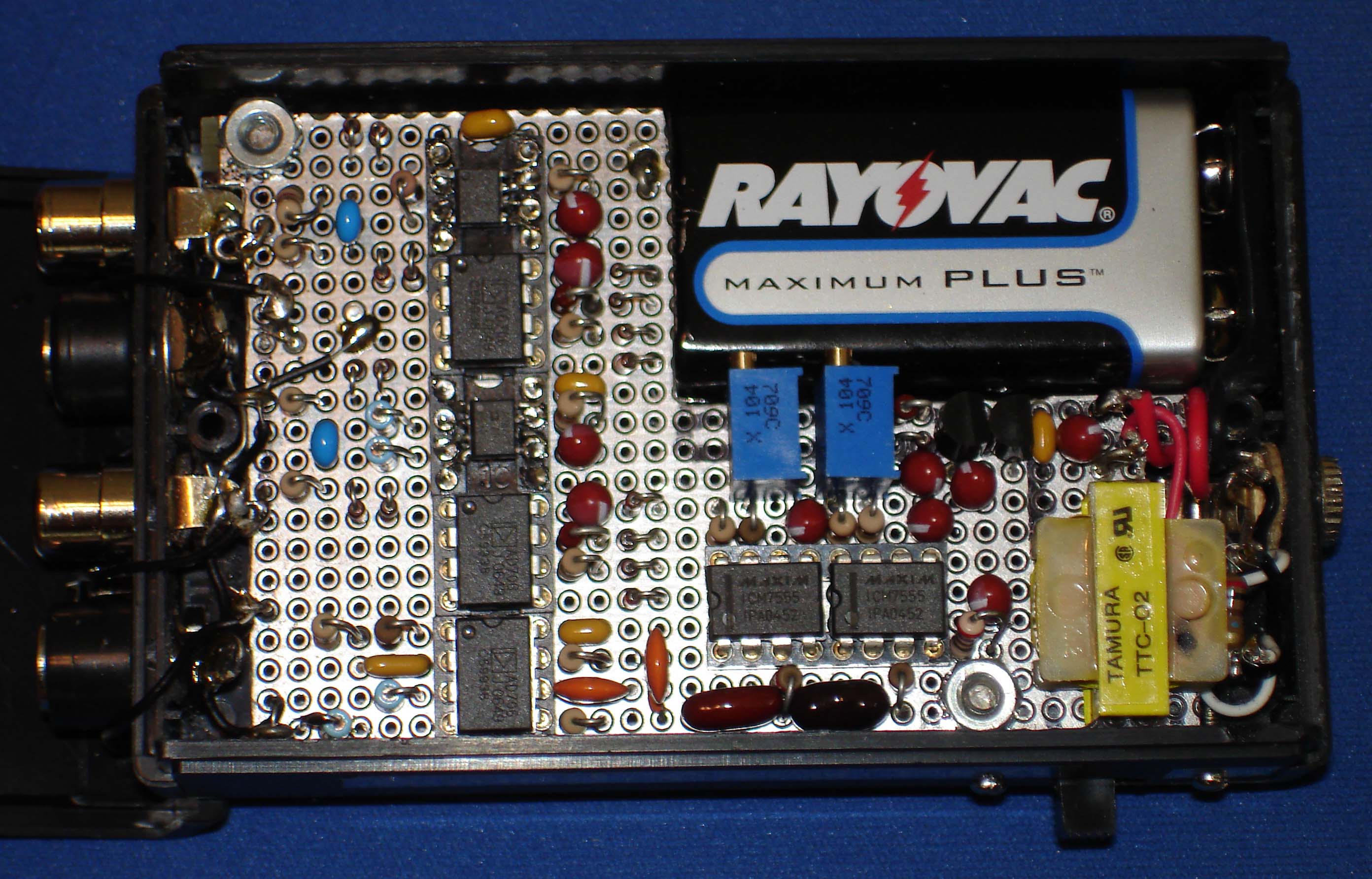
Dual Channel
FM Unit ( Revision 4)
Dual Channel FM
Unit Internal,
External (Revision 5)
Sixteen
Channel Multiplexed AM Bread-board
EEG Testing
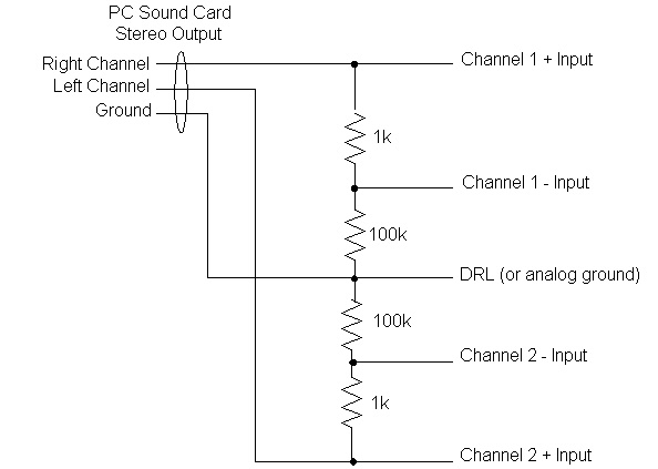
Low frequency EEG signals can be generated using another computer running the Dual Function Generator application (see this web site @ www.hotamateurprograms.com ) and an interface test circuit. A dual channel test circuit is shown in figure 1.
EEG Screen Captures
Articles
1. "Cursor Control Using EEG Signals from Eye Movement Potentials", Revision 1.
2. "AHMI Project", A PowerPoint presentation (2.3 MB) describing an interface project with an individual who had ALS.
3. "EEG Probe Presentation", A PowerPoint presentation (1.5 MB) depicting the sound card EEG technology.
4. "Realizzazione e Valutazione di un Sistema di Acquisizione Dati EEG a Basso Costo per Brain-Computer Interface", A PDF document (8 MB) containing Marco's thesis (in Italian) on EEG BCI technology and sound card implementation.
5. "Cursor Control Using Voice and Facial EMG Signals", by Grant Connell. A project using EMG signals with a dual channel AM sound card unit to control the screen cursor.
6. "Cursor Control Using EMG Signals and Morse Code", Preliminary; by Grant Connell. A project using EMG signals and Morse encoding for easy cursor control and fast text generation.
Home | EEG Sound Card | Program Information | Downloads | Previews | Feedback